|
Full Optical Layout
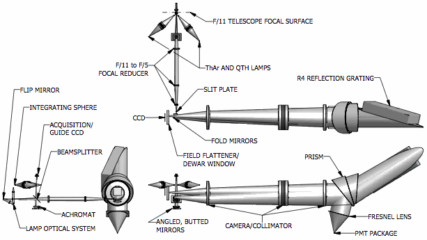
The PFS optical design is described in the
2006 SPIE paper and updated in the
2008 SPIE paper.
Lens Data
Element drawings for each custom optic and catalog numbers for each
commercial lens are available below.
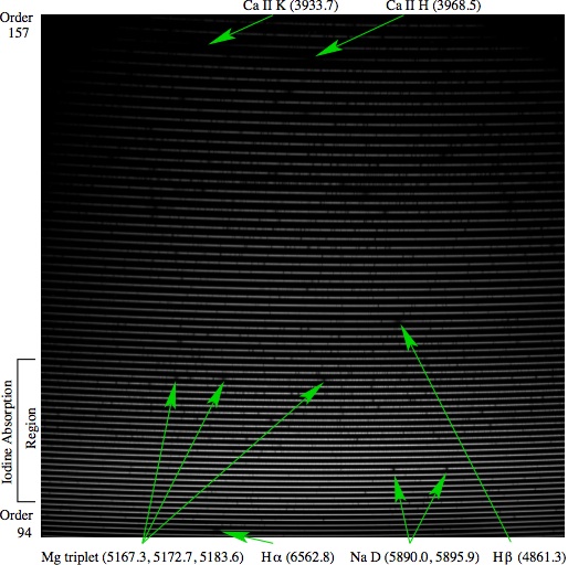
Spectral Format
The approximate echellogram is presented both as
lines tracing the center
of the free spectral range of each order, and as
discrete slit
images at specific wavelengths across the free spectral range of each
order. The latter shows the variation in the line tilt across the format.
The slit is tilted by 8.4 degrees so that the mean line tilt will be
vertical across the 500-620nm iodine absorption region. Only those orders
spanning 390 to 620nm are represented, although the PFS format extends to
668nm. A stellar spectrum taken with PFS is shown below with several
prominent absorption lines labeled.
|