Data Files
The COSMOS pipeline requires a number of data files as input, in addition to the CCD frames. Some are provided, but some must be generated by the user. Each is described below.
Image Files
IMACS
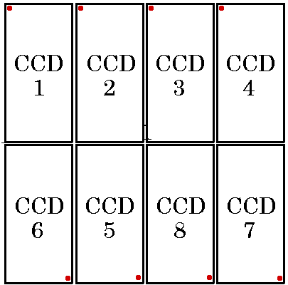
Each IMACS exposure produces 8 FITS image files, one for each CCD; These
have names ccdmmmmcn.fits,
if produced by the original SITE dewar, iftmmmcn.fits,
if produced by the current short camera dewar, or iffmmmcn.fits if produced by the
current long camera dewar, where mmmm
is the exposure sequence number and n
is the chip number. Note that the chips are not numbered in the expected order;
the arrangement of chips is as shown below. The red dot indicates the corner of
the CCD with pixel (0,0). If binning is set to 1, each image file is 2048x4096
pixels in size, after removal of bias lines and overscan.
LDSS3
The current LDSS3 CCD is 2048 x 4096 pixels, divided into two 2048 x 2048 segments, and each exposure produces 2 2048 x 2048 pixel fits files, with names ccdnnnnc1.fits and ccdnnnnc2.fits. For data analysis, these must be combined into a single FITS file using the program stitch.
CCD files produced by reduction programs have additional labels appended; for example
|
Bias corrected: |
|
|
Flat fielded: |
|
|
Sky subtracted: |
|
|
Spectroscopic flats: |
|
|
Mosaiced images: |
|
|
Extracted spectra: |
|
Note that some of these designations are hierarchical (i.e. flat-fielded implies bias-corrected, and sky-subtracted implies flat-fielded and bias- corrected).
Dewar Offset File
The dewar offset file defines the position offsets for a particular
instrument setup, including rotation, xy position, and scale. Default dewar
offset files exist in $COSMOS_HOME/sdata/dewoff
for most combinations of camera (long or short), each dewar mounting (Normal or
Nod&Shuffle) and each disperser. The IMACS names are constructed as shown
in the following tables:
|
+ |
|
+ |
|
||||||||||||||||||||||||||||||||||
Thus, for example, the dewar offset file for the long camera with the 300
l/mm grating and a nod & shuffle dewar mount is called LC300l_NS.dewoff. The LDSS dewar offset
file names are
|
+ |
|
||||||||||||||||||||||||
Thus, the dewar offset file for the LDSS3 instrument with the VPH blue grism
is called L3VPH_B.dewoff A
more accurate dewar offset file can be generated for an observation set using
the program align-mask. They can be adjusted manually using the program adjust-offset.
If defineobs is given the name of a fits file from a given observing
setup, it will automatically determine the correct default dewar offset file to
be used.
Important: note that the dewar offset file type, N or NS, corresponds to the dewar mounting, not the type of spectra obtained. In particular, IMACS Nod&Shuffle observations after April 2007 are taken with the dewar in the Normal mounting, and the _N dewoff files should be used.
Mask Definition File
The mask definition file is generated by the program maskgen which was used
to design the slitmask. Files names are of the form maskname.SMF.
Observation Definition File
The observation definition file defines a particular observational setup, including:
- Dewar (SITE, SITE2, E2V, Mos2, Mos3, LDSS2, or LDSS3)
- Camera (LONG or SHORT if IMACS)
- Mode (DIRECT or SPECTROSCOPIC)
- Disperser
- Disperser angle
- Disperser order
- Slit mask name
- Dewar offset file name
- Disperser misalignment
- Camera distortion file
Existing obsdef files should only be edited or new ones created from existing ones using the program defineobs. Note that disperser order and angle are only relevant for gratings, not for grisms (or direct).
Spectral Map File
The mapping of wavelength and slit position onto the individual CCDs is described by a spectral map file. Map files form the basis for all of the spectral reduction procedures. They are generated from the information in the mask definition and observation definition files using the program map-spectra. Using a comparison arc image, spectral maps can be improved using the program adjust-map.
Program Parameter Files
Most COSMOS programs have an accompanying IRAF-like parameter file, which modifies the program's behavior. These parameter files are edited by the program editpar. Programs search for their parameter files first in the directory defined by the environment variable COSMOS_PAR_DIR.
Bad Pixel Map
Maps of bad pixels in the dewars are contained in the files dewarname.badpix, located in $COSMOS_HOME/sdata/badpix. These maps
are needed by the reduction pipeline. Users may also create their own bad pixel
files, if desired. These files are tables, in which each line contains
information on one bad pixel group. The format of the first and all following
lines is:
Chip Xmin Xmax Ymin Ymax [Binning]
Chip Xmin Xmax Ymin Ymax
etc
The optional parameter Binning, on line 1 must be specified only if the bad
pixel group coordinates are NOT for 1 x 1 binning, and is either a one digit
number if the x and y binning is the same, or a two digit number if x and y
binning are different. For example, if x binning is 1 x 1 and y binning is 2 x
2, the Binning parameter will be 12. Note that bad pixel files of any binning
can be used in the reduction of data of any binning, the two need not match,
but it is clearly undesirable to use bad pixel files of higher binning than
that of the data to be reduced, i.e. do NOT use a 2 x 2 bad pixel file to
reduce 1 x 1 data. The bad pixel files provided in $COSMOS_HOME/sdata/badpix are all 1 x 1
binned.
New bad pixel maps, which include the locations of features from other spectral orders, which one might wish to mask out, can be created using the program badpixels.
The following files are not directly accessed by the user, but are described for completeness.
Dewar Definition File
The dewar definition file describes the physical layout of CCDs inside the
dewar, and has a name like dewarname.dewdef.
These files are located in the directory $COSMOS_HOME/sdata/dewdef.
Do not mess with these files! Because chip 6 of the IMACS SITE dewar was
changed on August 1, 2005, there are two dewdef files for the SITE dewar. The
currently existing files are:
|
Instrument/configuration |
Dewar Name |
|
IMACS w/SITE dewar before 01 Aug '05 |
SITE |
|
IMACS w/SITE dewar after 01 Aug '05 |
SITE2 |
|
IMACS w/E2V dewar |
E2V |
|
IMACS w/Mos3 dewar |
Mos3 |
|
LDSS3 before Jan 2014 |
LDSS3 |
|
LDSS3 after Jan 2014 |
LDSS3C |
Camera Distortion File
The camera distortion file describes the distortions in the short camera optics, which have varied with time. They have names of the form Shortn.distor, and are located in the directory $COSMOS_HOME/sdata/distor.
File Location
COSMOS expects all input files to be in the following locations:
- Dewar definition, distortion map, and default bad pixel
files in subdirectories of
$COSMOS_HOME/sdata/. The environment variable COSMOS_HOME is predefined (either by the system or by you when you installed the software) and should not be messed with. - default dewar offset files in the directory
$COSMOS_HOME/sdata/dewoff - Parameter files are looked for in the directory specified by COSMOS_PAR_DIR.
The following files are those manipulated by the user. It is recommended that these be located in the host computer file system rather than in the file system of the COSMOS virtual machine. See the instructions on using shared disks located in the VirtualBox documentation .
- All other data files are expected to be in the working data directory, unless you specify filenames with full paths.
- CCD fits files, i.e. bias, flatfield, comparison arc, and
object spectra, should be in the directory tree specified by the
environment variable COSMOS_IMAGE_DIR. For example, if COSMOS_IMAGE_DIR is
defined as
/home/joe_user/dataand your images are in/home/joe_user/data/night1, the file names should be specified asnight1/filename. If you want to keep both data files and image files in the same working directory, simply define COSMOS_IMAGE_DIR to be "." This is the default at startup. The value of COSMOS_IMAGE_DIR may be changed by using the usual system commands (i.e. setenv under csh), but the aliases scd and lcd (see programs) saves some typing.